Team Member: Yuan Chen, Yiting(Lora) Lu

Little D is a robot acting as a mailman,
deliver messages people can't express orally, or in person.
It acts as a courier for anyone in any relationship to help people express their feelings to the other person while protecting themselves' feelings as well.
Concept:
Some sentences just challenging to express, like:
I am sorry.
Elton John wasn’t kidding: Sorry does seem to be the hardest word. Some people find it so hard to apologize that getting them to admit to even the smallest wrongdoing involves a significant battle—often, a fruitless one. Although we might perceive the reluctance of these non-apologists as pure defensiveness or pride, a far deeper psychological dynamic is often at play: Refusing to apologize often reflects efforts to protect a fragile sense of self.
We need a courier in our relationships. Kids become couriers for their parents a lot. Our team wants to create a courier for anyone in any relation to help people express their feelings to the other person while protecting themselves’ feelings as well.

Source: Shutterstock
How it works:
This robot Little D sits on wheels powered by motors. It carries a display board, and moving randomly in the room. When Little D detects a person’s face through the camera on the top, it plays music to attracts the person’s attention. When he/she squats and pick up the cute little guy, he/she will see the message. In this way, Little D mitigates dramatically emotional moments, and provide possibilities to fix relationships.


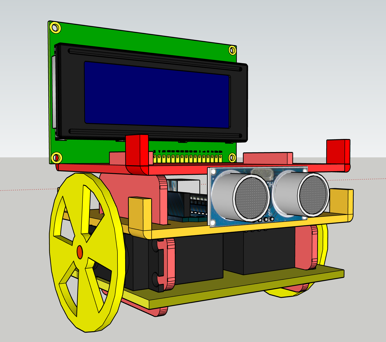
The Components:
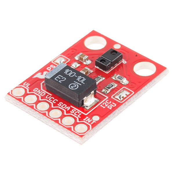
Distance Sensor is the eye of Little D.
It avoids the robot run into walls and table legs, and run around the space freely.

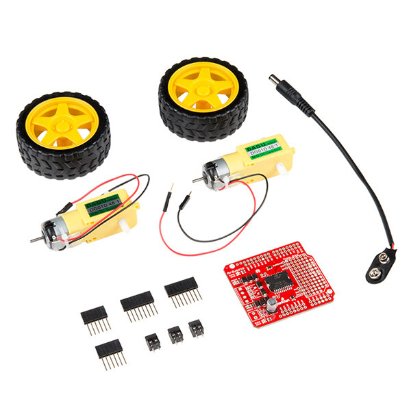
Little D is on wheels to approach the message receiver, and move around the space to attract people’s attention.
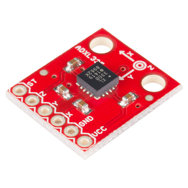
It is Little D’s eye. The camera detects a person’s face and triggers the buzzer to make sounds.
The sound will attract the message receiver’s attention.

When triggered, play music to attract people’s attention.

Display the message needs to be delivered.

The Building Progress:
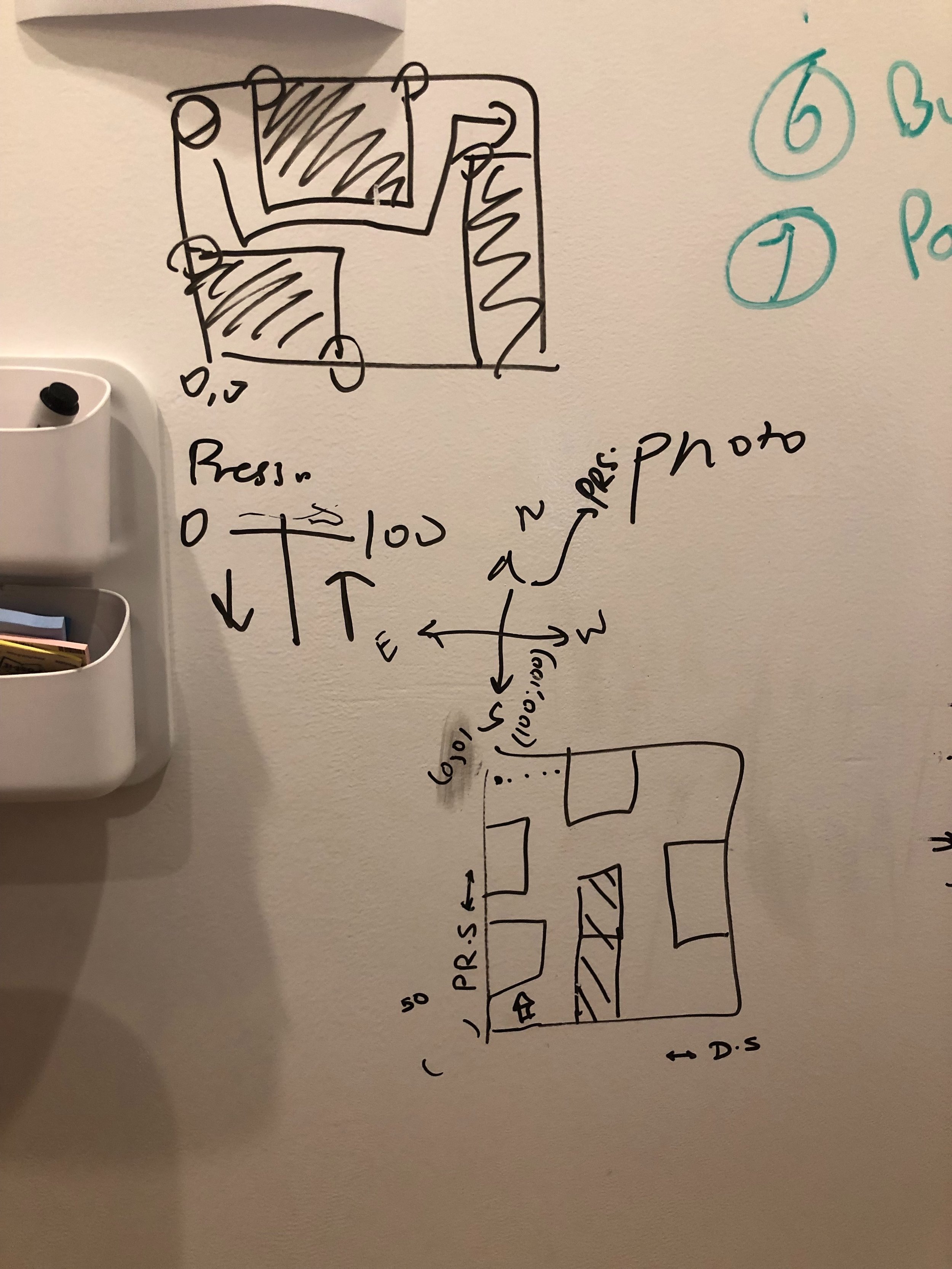
Sketch 1.0
The first draft demonstrates some essential functions Little D can have. The appearance and technical details had not been thought through at this stage.
Sketch 1: A robot on the wheel. We are considering display options, distance sensor, gesture detector.
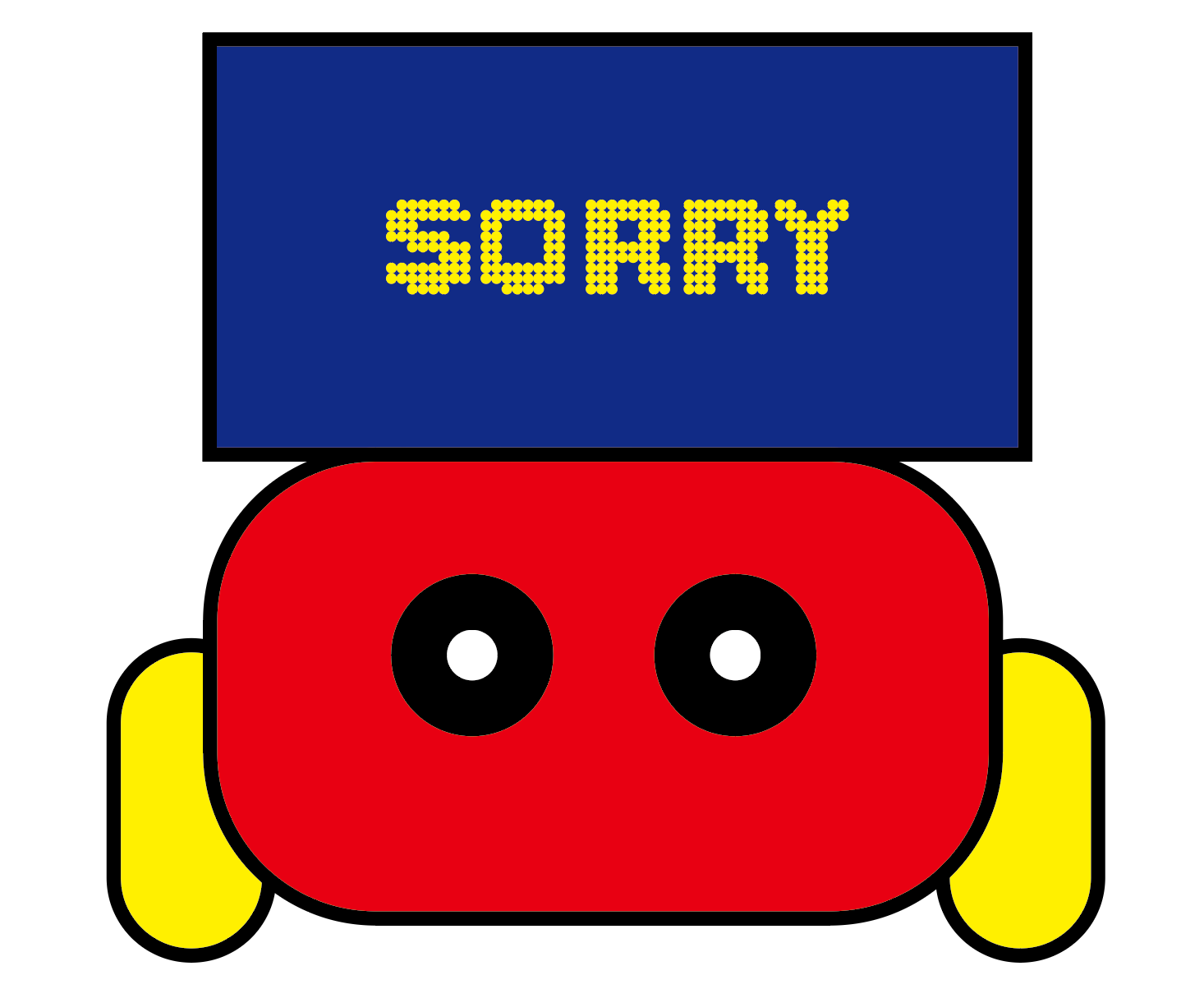
Sketch 2: We are wondering how to display the “sorry“ message in a much impressive way.
Test Sensor
1. The connection between motors and distance sensor.

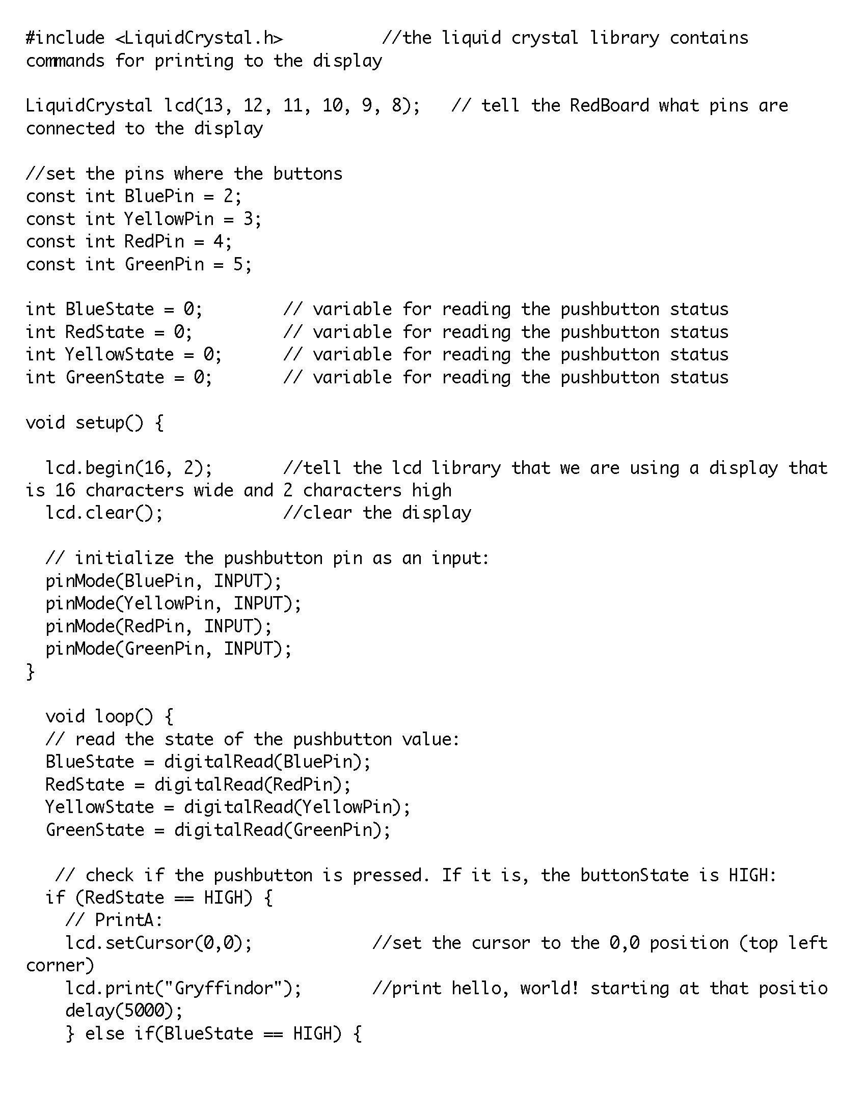
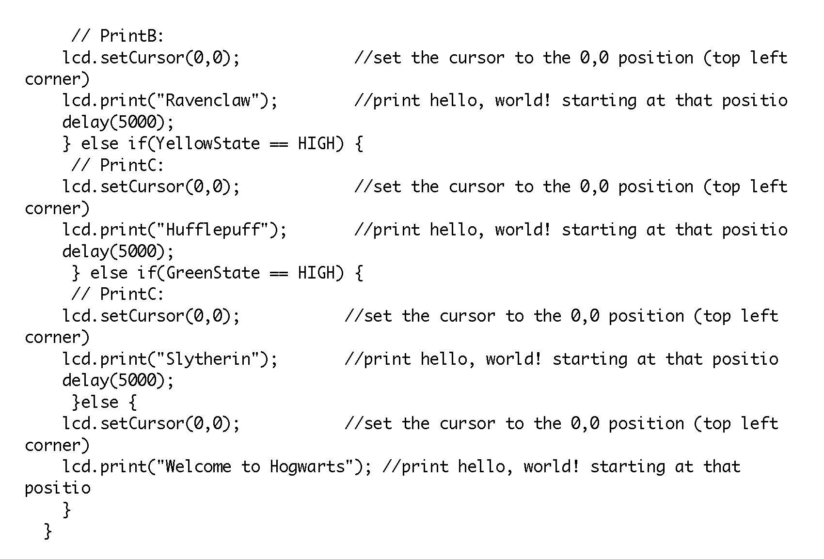
2. Add an LCD screen to display emoji and the message.

3. Test the robot in the studio. The robot runs in the space without bumping to anything.
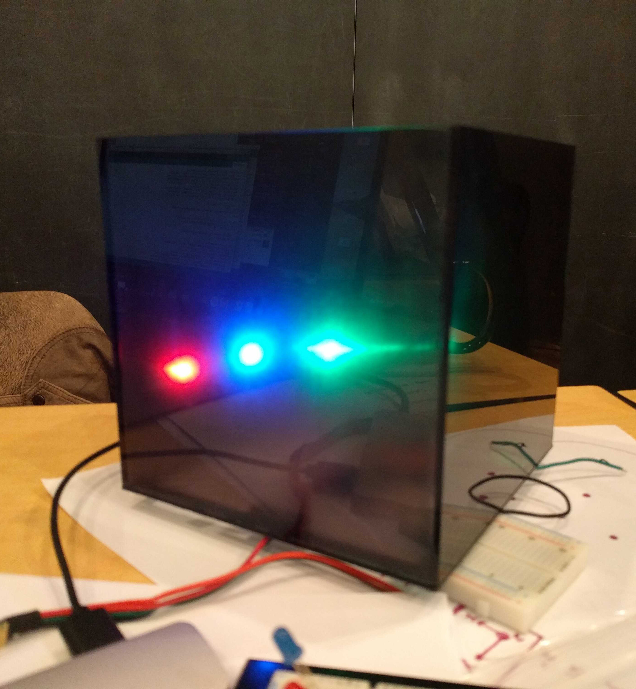
4. OpenMV camera talks to the Arduino board: When detecting a human face, light up the LED light bulb.
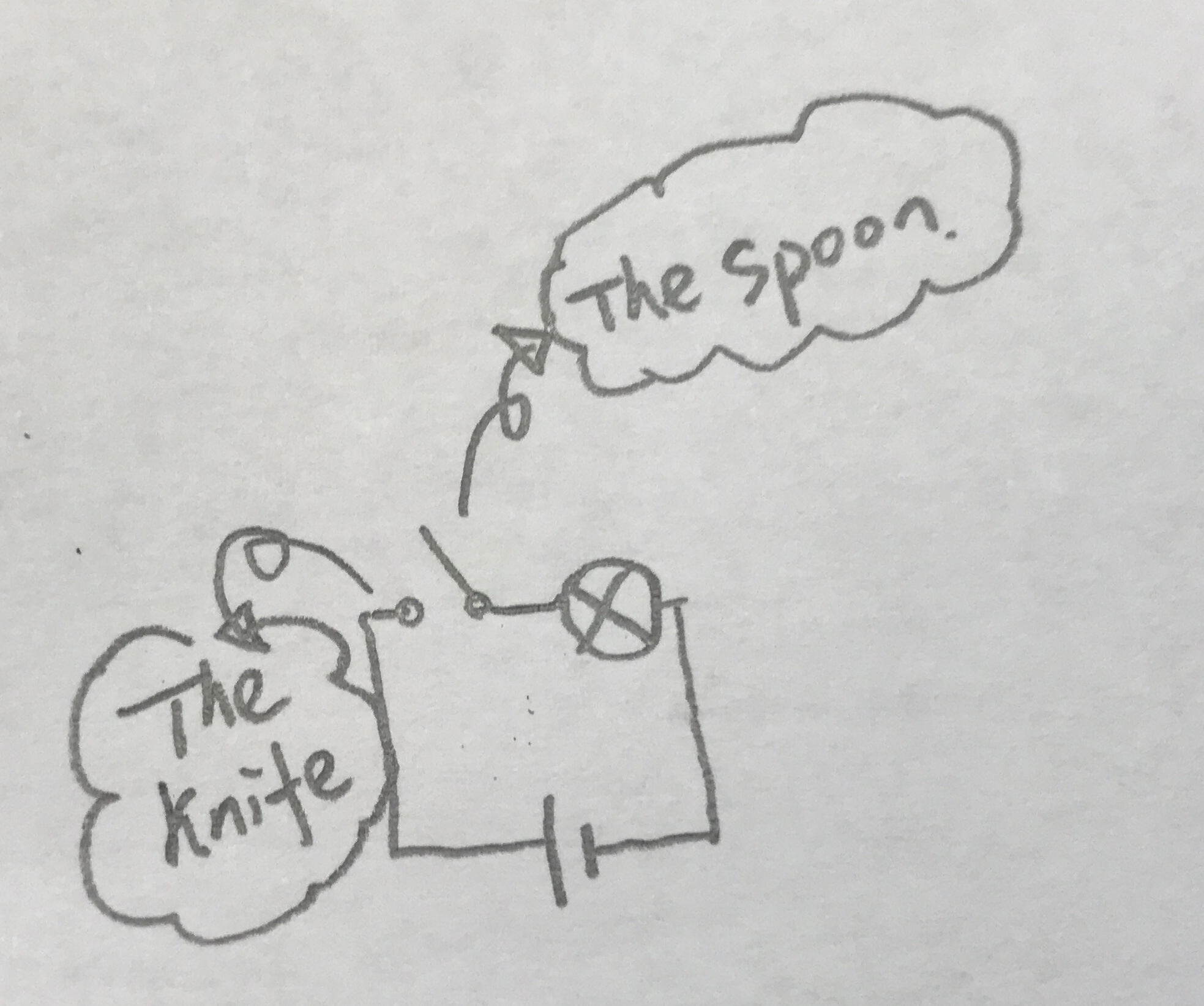
Schematics
Two Arduino boards run little D. One for connecting distance sensor, motor, and LCD. One for the connection between the buzzer and OpenMV Camera.