Team: Xiaofang Fan, Hyelim Lim, Yuan Chen, Bowen Shen
Cubeverse is a 6*6 inch interactive cube. The player constantly changes the lighting output inside the cube by flipping the cube around in hand. The playful experience helps the player to feel empowered and keep the world in hand.

Inspiration:
“Give me a firm spot on which to stand, and I shall move the earth.”
— Archimedes
Most of the time we humans are dissuaded by natural power from making moves. Our team shrinks the world to the size that a hand can hold, inspiring the player. This playful campaign demonstrates that even small actions make a difference. Even a small finger move counts. We hope the player will be inspired and without fear.


Concept: A PLAYFUL INTERACTIVE CUBE
By flipping the cube to certain angles, the player dramatically changes the visual in the ball (a.k.a. the “universe” in the ball). There are multiple options available for combining angles and directions.
Concept sketch


Process:
Research on sensors: Sensors That can detect movements:
Tilt Sensor
Tilt Sensor - AT407
This AT407 basic tilt switch can easily be used to detect orientation. Inside the can is a ball that make contact with the pins when the case is upright. Tilt the case over and the balls don't touch, thus not making a connection.
Accelerometer Sensor:
Triple Axis Accelerometer Breakout - ADXL335
Breakout board for the 3 axis ADXL335 from Analog Devices.
The sensor has a full sensing range of +/-3g.
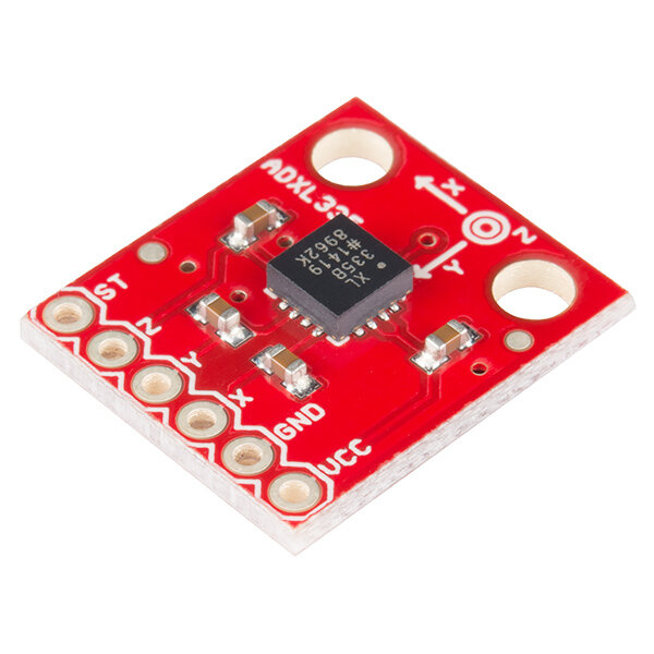

We chose the accelerometer out of these two options. The accelerometer has more adjustable features than the tilt sensor.
Research on materials
Lights:
LED strip has high flexibility and controllability.

Container
Our team chose black translucent acrylic sheets to build the container. Since we could not find readymade ones in the market, we ended up sanding a transparent grey acrylic sheets to achieve our goal.
Glue
Surprisingly, finding the right glue is a laborious job.
After testing several kinds of glue, including school glue and hot glue gun, we ended up using acrylic glue to put up the cube-shape container.

Get set up!

Glue all the parts together precisely.
Structure Design

Brainstorming!

The final sketch
We're looking for a way that LED lights can blink in a 3-demential area, not just show on 2D flat surfaces. Upon multiple tests, we found that the closer the LEDs to the acrylic plates, the less illusion the lights would offer. In fact, being too close to the surface produces hot spots of light on the surface. We decide to build a structure inside the container to keep the LEDs to the exact position as expected.
We placed all the components onto an opaque black acrylic plate, including LED lights, a circuit board, and batteries. This portable foundation makes our debugging process and other inspections much easier.

Building the container.

Glue down all the components.

Stretch LED lights onto the beams.
Test the illusion effect.
Schematics

How the codes work
Code for this project can be found here.
Tilt detection:
The accelerometer reads three values: x, y and z. Through experimentation, we found that the orientation of the tilts could be differentiated by the changes in the 3 values compared to the baseline values (when the cube is sitting flat, upright, and upside down)


LED mapping:
After finding a way to detect different tilt orientations, we need to translate it into LED patterns. Since all LEDs are on the same strip, the way to control a particular LED is to call its index [ note that it is Zero-based numbering ] in the array. We've numbered all of the LEDs.

When the cube is tilted, if it is a "edge tilt," the two LEDs on the edge are lit up; if it is a "corner tilt," the LED at the corner is lit up. When the cube sits flat, all of the center LEDs light up.


Calibration:
When we tested the circuit with a laptop, we used hardcoded average baseline values based on observation. From the serial monitor, we noticed that the baseline reading could be slightly different every time, and therefore we thought about a calibration function. Since the fluctuations are insignificant, this function is not a must-have.
However, once we swap the power with a 9V battery, the circuit responded inappropriately to the movements. Our assumption is that the baseline values have changed, so we've had to calibrate them every time the program runs.
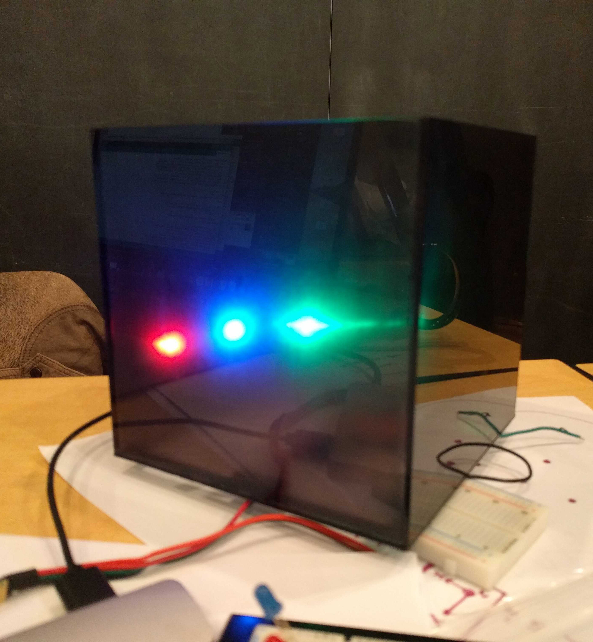
This calibration process has two states— “upright” and “upside down”. The baseline values can be slightly different in these two states. The cube automatically starts to calibrate the upright state once it is switched on. When the calibration of the upright side is finished, is the LED lights at the base will be lit up in green. Flip the cube upside down, wait several seconds for the cube to finish the calibration process. Once it’s done, all the LED lights are lit up in green for one second, changed to purple, and start working.
Reflection:
What worked well:
The LED lights generally respond to the movement accurately.
The dark acrylic surface is well resonated with our concept of the universe.
The light is well diffused.
The whole object is self-contained. There’s no instruction needed before having hand-on experience.
What didn’t work well, or could be improved:
The changing pattern could be more gradual and accurate by calculating how much the cube is getting tilted.
It is possible to increase the number of LEDs without worrying that the power might run low, since LED lights are not lighting up at the same time. This feature could also help us create a more gradual change.
The effect becomes not as accurate when the cube is sitting on the sides, since we only coded for two states (upright and upside-down).
The shadows of the wires and pillars are more obvious than we expected. Could have been improved by increasing the distance between the pillars and the exterior cover, changing the interior design or using a more diffusive material.
The behavior of the LEDs could be more lifelike and natural. For example, when there are no movements, the central LEDs could change brightness softly as if it is breathing; when the cube remains inactive for a while, the LEDs get dimmer.
The calibration process can be improved. For now, it is not so intuitive and the user can not do it without learning instructions.
Because the LEDs on the strip is only facing one way, it is hard to see the light from other directions.